 Rendering with Radiance
Rendering with Radiance
Rendering with RadiancePlate 1. A Radiance rendering of a conference room. (Model created by Anat Grynberg and Greg Ward.)
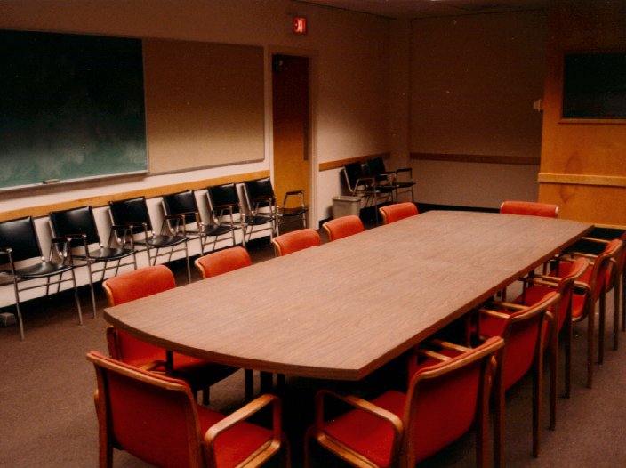
Plate 2. A photograph of the conference room simulated in Plate 1.
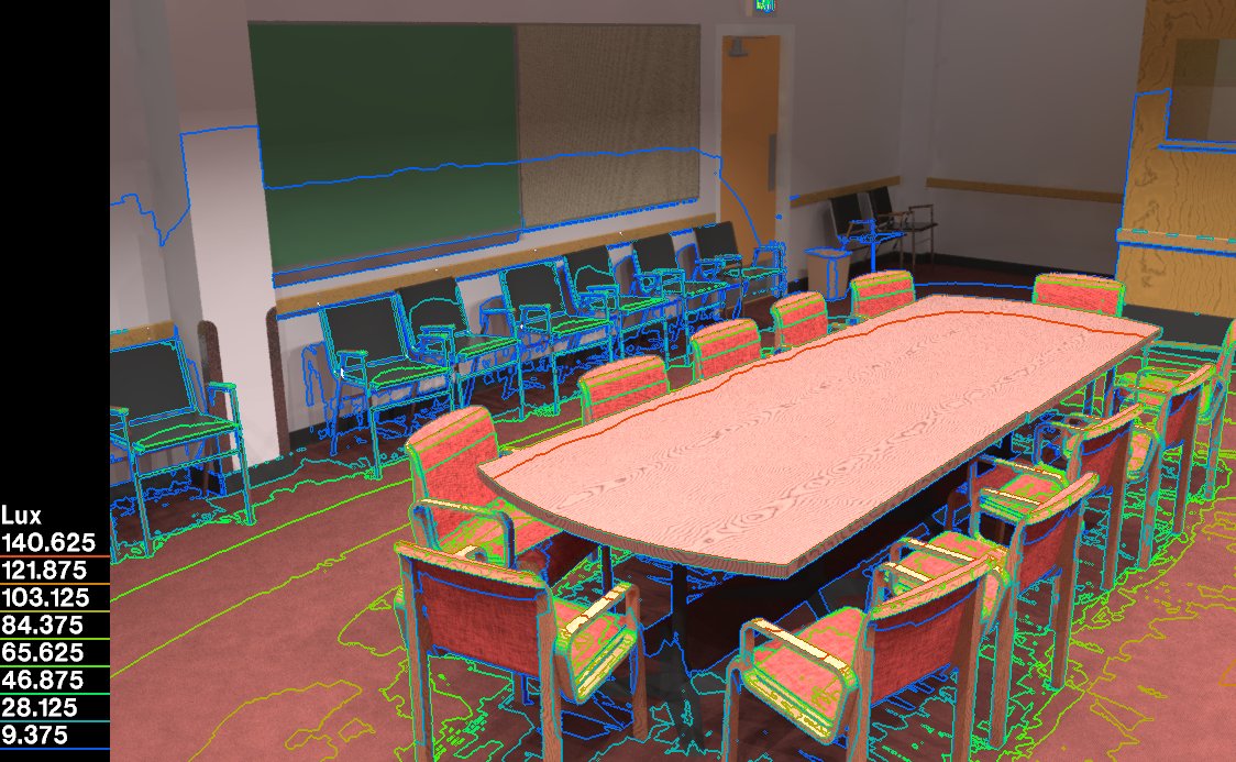
Plate 3. A simulation of the conference room with superimposed isolux contours (i.e., lines of equal illuminance). This emphasizes the numerical nature of the results, showing information that is critical for lighting analysis.
Plate 4. A Radiance rendering of a daylighted office space. (Model by Raphael Compagnon and Jean-Louis Scartezzini.)
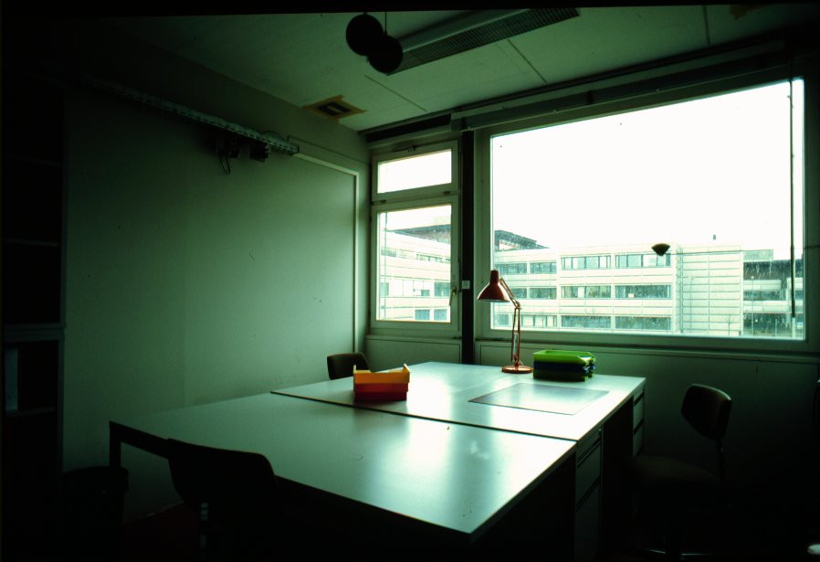
Plate 5. A photograph of the office simulated in Plate 4.
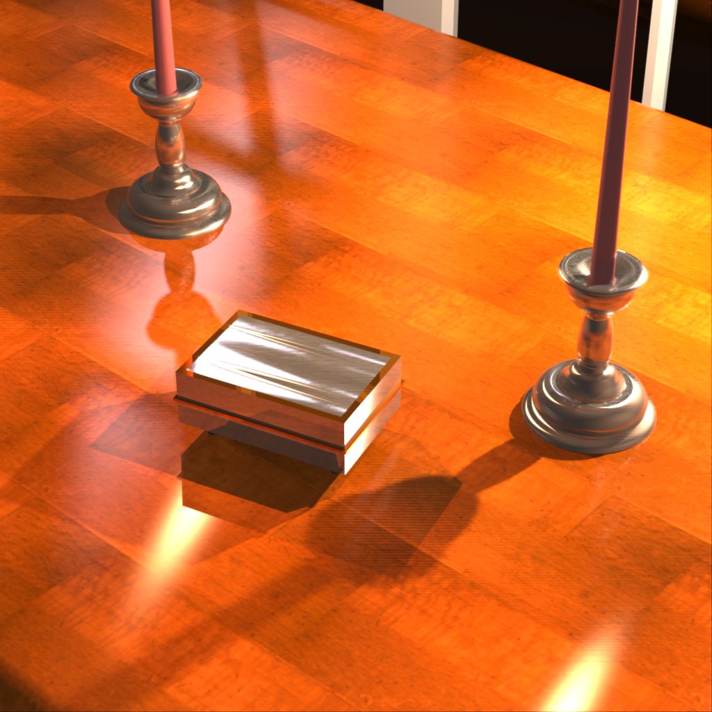
Plate 6a. A model showing anisotropic reflection functions and patterns that may be defined in Radiance.
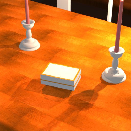
Plate 6b. The same model as Plate 6a, but with diffuse reflection functions as they might be modeled in a radiosity system.
Plate 7. The interior of the Indiana University Mellancamp Pavilion as rendered by Radiance. Input was translated from AutoCAD input. (Model created by Scott Routen and Rueben McFarland.)
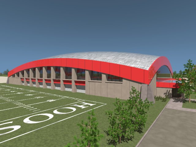
Plate 8. The same model shown in Plate 7, rendered from the exterior.